GAA26800AR2 Electronic Board Product Manual
1. Product Overview
|
Item |
Specification |
|
Product Name |
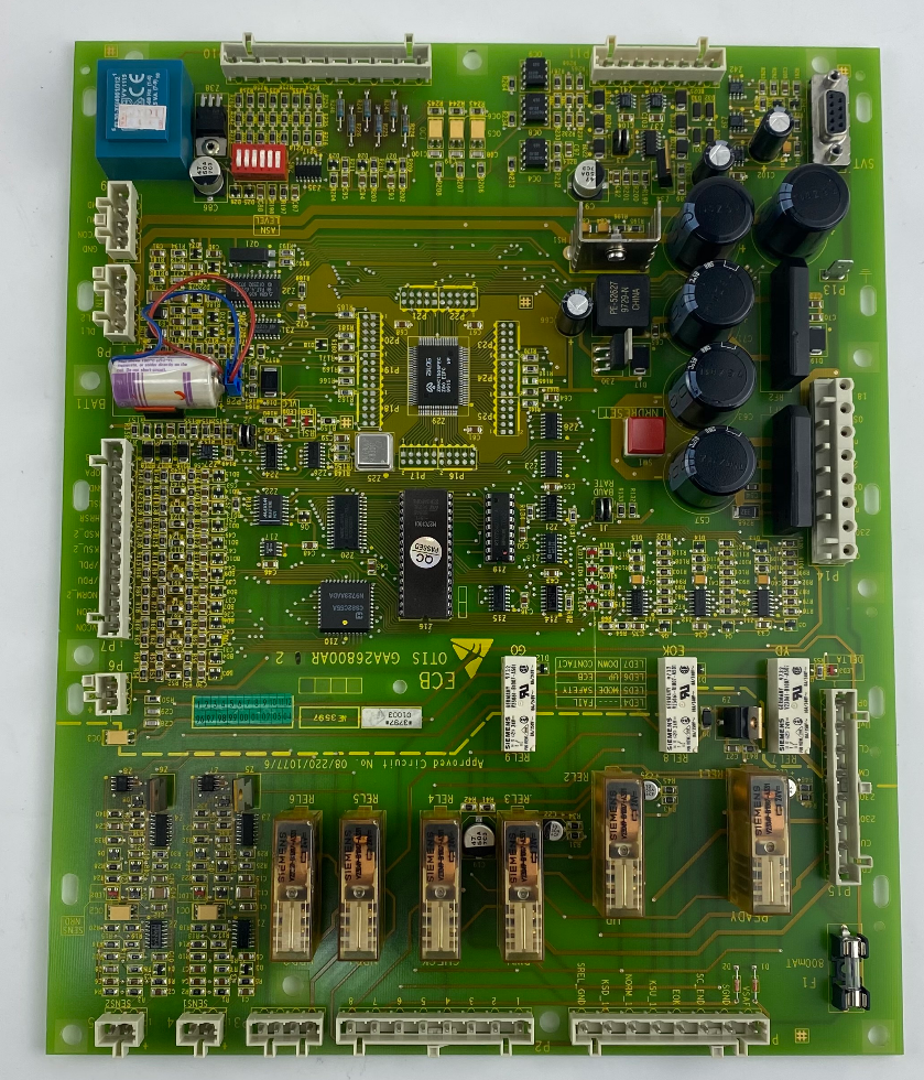
OTIS ECB Elevator Main Control Board |
|
Model |
GAA26800AR2 |
|
Applicable Brand |
OTIS, Xizi OTIS |
|
Main Purpose |
Core control unit of automatic elevators |
|
Application Scenarios |
Shopping malls, metro stations, airports, office buildings, hospitals and other public places |
|
Brief Summary: GAA26800AR2 is the dedicated main control board for OTIS elevators. It undertakes all core functions including elevator startup, shutdown, speed regulation and safety protection. |
2. Product Features
• Industrial Grade Quality: Adopts grade A PCB material, sturdy and durable with low failure rate.
• Wide Environmental Adaptability: Runs stably from -20℃ to 70℃.
• Plug-and-Play Design: Standard interfaces and clear wiring layout for quick replacement.
• Multiple Safety Protection: Built-in safety chain fuse (F1, 800mAT), the elevator will stop automatically once abnormality occurs.
• On-board Fault Diagnosis: LED indicators display fault codes directly for easy maintenance.
• Energy Saving Mode: Supports automatic speed adjustment according to passenger flow to save power.
Original Standard Configuration: Traceable serial number, compatible with official commissioning and remote diagnosis.
 3. Technical Parameters
3.1 Power Supply Parameters
3. Technical Parameters
3.1 Power Supply Parameters
|
Item |
Standard Specification |
|
Main Input Power |
AC110V / AC220V, switchable via onboard DIP switch |
|
Internal Logic Power |
DC24V, converted by isolated onboard switching power supply |
|
Standby Power Consumption |
≤18W |
|
Full-load Power Consumption |
≤35W |
|
Backup Battery |
3.6V lithium battery, data storage life ≥ 5 years |
|
Fuse Specification |
Two independent fuses (5A / 10A), spare fuses are included |
3.2 Signal Isolation & Communication Parameters
|
Item |
Standard Specification |
|
Input Circuits |
32-channel DC24V passive switch signals (safety circuit, door lock, shaft limit, inspection, fire alarm, overload) |
|
Isolation Optocoupler |
TLP523 (DC signal isolation), TLP561J (AC load isolation, zero-cross triggering) |
|
Optocoupler Withstand Voltage |
2500Vrms, UL1577 certified |
|
Communication Interfaces |
RS232 debug port, parallel floor bus, door operator serial bus, car operating panel communication port |
|
Relay Output Specification |
6 independent electromagnetic relays, single contact load: AC220V 3A |
3.3 Physical & Environmental Parameters
|
Item |
Standard Specification |
|
PCB Material |
FR-4 flame-retardant industrial PCB, double-layer copper foil |
|
Installation Method |
4-point screw fixing for control cabinet, standard universal mounting holes |
|
Certification |
CE certification for elevator equipment |
|
Operating Temperature |
-20℃ ~ +65℃ |
|
Relative Humidity |
≤90%, no condensation or water accumulation |
|
Net Weight |
Approx. 0.75kg |
|
Package Size |
280×220×40mm (individually packed with anti-static vacuum bag) |
|
Dimension Note: Standard ECB board size, fixed by four corner screws, total weight approx. 1kg. |
4. Main Functions
|
Function |
Description |
|
Start & Stop Control |
Realize smooth startup and shutdown of elevator |
|
Speed Regulation |
Automatically adjust running speed according to passenger flow for energy saving |
|
Direction Control |
Control upward and downward operation of elevator |
|
Safety Monitoring |
Real-time monitoring of emergency stop, handrail, steps and other safety switches |
|
Fault Alarm |
Stop operation immediately and display fault codes when faults are detected |
|
Communication |
Exchange data with frequency converter, call boxes and other components |
5. Installation Instructions
5.1 Safety Warnings
• Only certified professional elevator technicians are allowed to operate.
• Cut off the main power supply of the elevator before installation.
• Hot plugging and unplugging are strictly prohibited.
5.2 Installation Steps
1.
Power Off: Turn off the main power and confirm power cut with a multimeter.
2.
Remove Old Board: Take photos to record all wiring positions, unplug connectors and remove fixing screws.
3.
Install New Board: Place GAA26800AR2 in position, align with screw holes and tighten screws.
4.
Wiring: Reconnect all connectors according to photos or drawings. (Note: Connect 24V AC power to P14-4/P14-5)
5.
Inspection: Confirm F1 fuse (800mAT) is intact and no short circuit exists.
6.
Power-on Test: Switch on the power, check indicator status and perform low-speed trial operation.
|
Tip: Take photos before disassembly to avoid wiring mistakes. |
6. Operation Instructions
Normal Startup
Switch on main power → Board indicators light up → No fault code displayed → Elevator starts running normally.
Indicator Definition
• Green light steady on: System operates normally
• Red light flashing / Digital code displayed: Fault occurs, please refer to fault code list
7. Quick Reference for Common Fault Codes
|
Fault Code |
Fault Description |
Troubleshooting Suggestion |
|
0010 |
Frequency converter communication failure |
Check CAN communication cables |
|
0216 |
Brake fails to release |
Inspect brake coil and mechanical structure |
|
162 |
Drive chain broken |
Adjust drive chain tension |
|
165 |
Step damaged |
Adjust the gap between striker and step to 3mm |
|
F1 Fuse Blown |
Safety circuit power cut |
Replace with 800mAT fuse of the same specification |
|
Note: Please refer to official OTIS GECB manual for complete fault code list. |
8. Important Notes
1. Non-professional personnel are forbidden to disassemble or modify this main board.
2. Power cut is required before installation to avoid board damage or personal injury.
3. Only use original 800mAT slow-blow fuse for replacement; ordinary fuses are not acceptable.
4. The board shall be installed in dry and dust-free control cabinet and kept away from water.
5. Store the board in cool and dry place when it is not used for a long time.
6. Regularly check loose wiring and dust accumulation every 6–12 months.
9. Packaging & After-sales
•
Packaging: Anti-static bag + thick carton, shockproof and moisture-proof.
10. Summary
GAA26800AR2 is a dedicated main control board for OTIS elevators. It is reliable, easy to install and equipped with built-in fault code display, which is an ideal choice for elevator maintenance and system upgrade.
• Suitable for elevators in shopping malls, metro stations, airports and other public places
• Original factory quality, compatible with mainstream platforms such as 510PSE and 506NCE
• Equipped with 800mAT safety fuse for multi-level protection
|
Disclaimer: This manual is for reference only. All installation and commissioning shall comply with OTIS official technical manuals and be operated by certified professional technicians. |


 ADD: UNIT 04, 7/F BRIGHT WAY TOWER No.33 MONG KOK RD KL